






Home > Knowledgebase > Guides > How to Calculate Sheet Resistance Using the Four-Point Probe Method
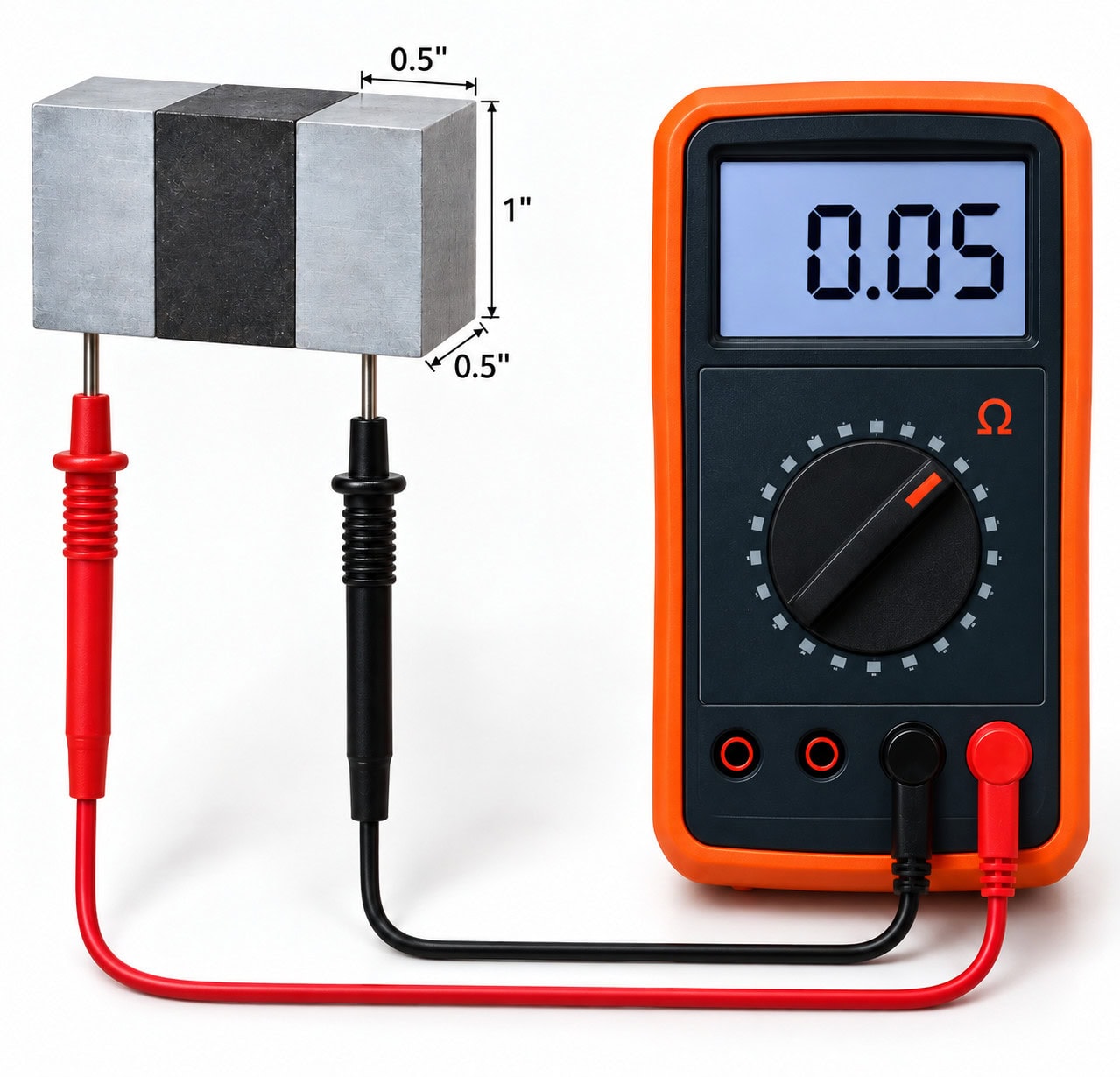
One of the quickest ways to verify a conductive coating has been applied correctly is to measure its electrical resistance. When the coating geometry is known, the measured resistance can be converted to sheet resistance, allowing coatings of different specimen dimensions to be compared. In our quality control resource guide, we suggest a simple methodology consisting of a jig and multimeter tool.
With this setup, the probes are connected to aluminum prisms with a square surface measuring 0.5” x 0.5”. The aluminum prisms are separated by an equally sized prism of an insulating plastic. With this setup, the distance between electrodes (L) is 0.5” and the contact width is also 0.5” (W). Since these distances are equivalent, the resistance measured along a conductive surface is the sheet resistance in Ohms/sq.
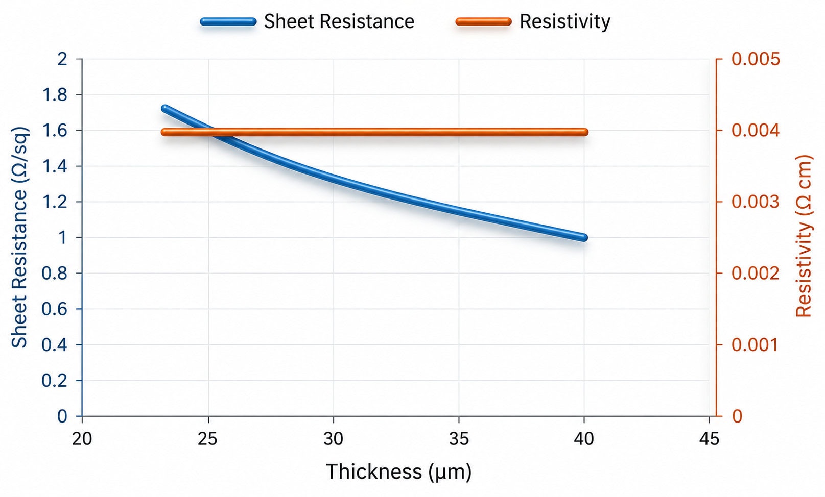
Some users, however, may be more familiar with using a four-point probe to characterize conductive coatings. We previously discussed this technique in our article on measuring resistivity. To clarify, sheet resistance is a property that is dependent on film thickness whereas resistivity is an intrinsic property of the material and converges on a constant value. The two measurements are related through the equation
Rs = ρ/t
Rs – Sheet resistance
ρ – Resistivity
t – Coating thickness
Figure 2 illustrates the difference between sheet resistance and resistivity as a function of coating thickness.
This article walks the reader through a simple calculation to determine the sheet resistance of a conductive coating using the 4-point probe method. The instrument contains 4 co-linear pins arranged in a Kelvin configuration with the outer 2 pins connected to a current supply and the inner pins connected to a voltmeter. Figure 3 below shows the basic setup for this.
Calculating resistivity using this method holds if we treat the conductive strip as a uniform rectangular conductor.
Samples are prepared for measurement by applying parallel strips of conductive coating on the substrate. Once cured, the thickness and width of the strips is measured. The probe is placed onto the conductive strip where the voltage drop is measured between the 2 inner pins shown in figure 3. Since the current supply is constant, the resistance of the film can then be calculated using Ohm’s law
R = V/I
V – voltage drop between the inner pins
I – current supplied to probe through the outer pins
R – calculated resistance measured over the length of the inner pins
Earlier, we defined sheet resistance as
Rs = ρ/t
The equation for resistivity using this 4-point probe method is
ρ = R*A/L
ρ – resistivity
R – measured resistance
A – cross-sectional area of trace [trace width(W)*coating thickness(t)]L – length the voltage drop is measured (this is the distance between the inner pins or 1”)
So we can now substitute and write
Rs = (RWt/L)/t
Simplifying this equation gives
Rs = R *W/L
The equation calculates the sheet resistance from the resistance calculated from the voltage drop measured within the inner pins on the 4-point probe. With the 4-point probe method, W < L so Rs < R. You must use common units for both W and L, so if L is 1” or 2.54cm, W must be expressed in either inches or cm.
Customers that use sheet resistance measurements as a quality verification must remember that resistance is inversely proportional to coating thickness, meaning the sheet resistance decreases as the coating becomes thicker
Rs ∝1/thickness
Customers can use the sheet resistance values published on the product technical data sheet for reference but should not aim to achieve an exact match. For quality control, values within the same order of magnitude as published values indicate the coating has been successfully applied.
Talk to MG Chemicals and let us be your trusted partner. Our technical specialists work to identify practical solutions that improve performance, mitigate risk and keep projects moving. Our focus will always be solution first and we offer unlimited levels of advice.
Let’s start a conversation.
"*" indicates required fields
1-800-340-0772 / 905-331-1396
"*" indicates required fields


